Stretch Cluster notes
Clustering

At work, very often we need to implement disaster recovery solution. One of the methods to achieve this is to implement stretch clusters.
A computer cluster is a set of computers that work together so that they can be viewed as a single system. Computer clusters have each node set to perform the same task, controlled and scheduled by software.
The components of a cluster are usually connected to each other through fast local area networks, with each node (computer used as a server) running its own instance of an operating system. In most circumstances, all of the nodes use the same hardware and the same operating system.
Clusters are usually deployed to improve performance and availability over that of a single computer, while typically being much more cost-effective than single computers of comparable speed or availability.
Stretched Clusters
A very special case of clusters is when instead of using a Local Area Network, we connect them over a Wide Area Network.
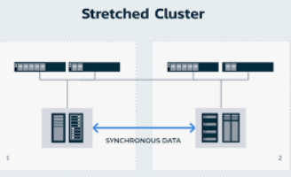
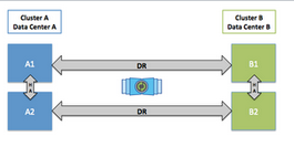
For disaster recovery with low Recovery Point Objective (RPO) requirements, using stretched clusters to keep data synchronized accross data centers is a very common approach.
These typically you would have cluster nodes spread across two locations. With data being replicated synchronously between them. Latency over the Wide Area link becomes quite important as usually, synchronous protocols would require acknowledgement from cluster node members on the far away location before completing a transaction.
Another name for Stretched Clusters is geo-replicated clusters.
Calculating latencies
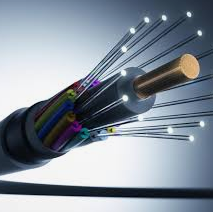
Latency is a term that is used to describe a time delay in a transmission medium such as a vacuum, air, or a fiber optic waveguide. In free space, light travels at 299,792,458 meters per second. This equates to 299.792 meters per microsecond (µs) or 3.34µs per kilometer. In fiber optics, the latency of the fiber is the time it takes for light to travel a specified distance through the glass core of the fiber. Light moving through the fiber optic core will travel slower than light through a vacuum because of the differences of the refractive index of light in free space and in the glass. See m2optics on how to calculate the latency based on the distance.
A rule of thumb for quickly calculating latency for every 100 Km add 1 ms round trip latency. This based on single mode fiber is using 5 microseconds per kilometer over a straigth line distance between locations. This provides a high level estimate of predicted latency. This estimate is enough to eliminate possible options that one may be considering when implementing a DR solution.
Common storage stretched clusters
These are common solutions for storage replication that implement stretched clustering:
- Ceph - a free and open-source software-defined storage platform that provides object storage, block storage, and file storage built on a common distributed cluster foundation.
- VMware vSAN - a software-defined storage that is embedded in VMware's ESXi hypervisor.
- NetApp Metrocluster - a feature of NetApp's ONTAP software. It allows to synchronously replicate data between two sites using SyncMirror.
Ceph

Ceph provides distributed operation without a single point of failure and scalability to the exabyte level. Ceph does not rely on any other conventional filesystem and directly manages HDDs and SSDs with its own storage backend BlueStore and can expose a POSIX filesystem.
Ceph has a stretch mode that supports geo-replicated clusters.
A stretch cluster is a cluster that has servers in geographically separated data centers, distributed over a WAN. Stretch clusters have LAN-like high-speed and low-latency connections, but limited links. Stretch clusters have a higher likelihood of (possibly asymmetric) network splits, and a higher likelihood of temporary or complete loss of an entire data center (which can represent one-third to one-half of the total cluster).
Ceph is designed with the expectation that all parts of its network and cluster will be reliable and that failures will be distributed randomly across the CRUSH map. Even if a switch goes down and causes the loss of many OSDs, Ceph is designed so that the remaining OSDs and monitors will route around such a loss.
Sometimes this cannot be relied upon. If you have a "stretched-cluster" deployment in which much of your cluster is behind a single network component, you might need to use stretch mode to ensure data integrity.
Ceph has two standard configurations:
- Configuration with two data centers (or, in clouds, two availability zones).
In this configuration, each site needs to hold a copy of the data. A third site is required as a tiebreaker monitor. This tiebreaker monitor picks a winner if the network connection fails and both data centers remain alive. - Configuration with three data centers (or, in clouds, three availability zones).
Because there is an odd number of sites, there is no tiebreaker monitor required.
RedHat in OpenShift implementations recomments a 10 ms RTT between sites, with 100 ms RTT for the tiebreaker monitor. This translates to 1,000 Km distance. The real limitation would be application itself, as 10 ms latency for disk writes is quite high.
Ceph also support asynchronous replication using rbd-mirror. This
does not have a latency limitation, with the disadvantage that RPO can not be zero.
VMware VSAN
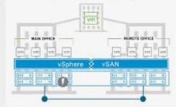
The vSphere and vSAN software runs on industry-standard x86 servers to form a hyper-converged infrastructure (or HCI). However, network operators need to have servers from HCL (Hardware Compatibility List) to put one into production.
Some vSAN features:
- native data at rest encryption
- local protection for stretched clusters
- analytics
- optimized solid-state drive performance
The latency limits for stretched vSAN clusters is documented in the vSAN network requirements documentation:
| Site Communication | Bandwidth | Latency |
|---|---|---|
| Site to Site | Minimum of 10 Gbps | Less than 5 ms RTT |
| Site to Witness | 2 Mbps per 1,000 vSAN components |
|
The latency of 5 ms RTT translates to a maximum of 500 Km distance.
NetApp MetroCluster
NetApp MetroCluster configurations combine array-based clustering with synchronous replication to deliver continuous availability, immediately duplicating all of your mission-critical data on a transaction-by-transaction basis. MetroCluster configurations enhance the built-in high availability and nondisruptive operations of NetApp hardware and ONTAP storage software, providing an additional layer of protection for the entire storage and host environment.
Latency requirements are documented in MetroCluster consierations for ISLs.
- The ISL speed must be least 10Gbps.
- ISL can be no further than 300km and the max RTT cannot exceed 3ms – whichever is reached first.
Conclusions

In general a 3 to 5 ms RTT is a reasonable figure. So usually between 300 to 500 Km distances.
Recap of solutions:
- Ceph - open source, software define storage solution
- VMware vSAN - closed source, software defined storage solution
- NetApp MetroCluster - Hardware based storage solution